 |
Figure 13: As the previous figure but the Cn2(h) profile is now scaled by h5/3 in order to illustrate the change in contribution to isoplanatic errors of the higher altitude layers |
The observing sites considered are:
Fig. 11a; La Palma, Canaries (JKT 1 m) in November 1996,
Fig. 11b; Siding Springs, Australia (40 inch) in January 1997,
Fig. 11c; Calar Alto, Spain (2.2 m) in April 1997.
Each figure shows three consecutive Cn2(h) profiles, each calculated
from a 7 second block of data (corresponding to 2000, 1.6 ms exposure, data
frames) - each block being separated by around 10 seconds.
For each figure, the first profile is shown as a solid line, the second as a
dotted line and the third as a dot-dashed line.
Using the methodology outlined in Sect. 3.4, the RMS error of each
Cn2(h) profile shown is estimated to be within 6![]() .Also shown within each figure is the average speed and PA-direction of
each dominant turbulent layer over the time interval covered.
.Also shown within each figure is the average speed and PA-direction of
each dominant turbulent layer over the time interval covered.
 |
The three sets of profiles appear remarkably similar in both their general form and as such share a number of interesting characteristics. Firstly, each set of Cn2(h) profiles appear to be highly discretised. In fact this phenomena is seen in all of the Cn2(h) profiles we have calculated to date such that at any particular moment the optical turbulence appears to be dominated by a small number (perhaps 2-4) of thin layers. Because of the intrinsic SCIDAR resolution (Sect. 3.3), the actual thickness of these layers is difficult to ascertain. However in many cases the apparent thickness corresponds closely to that expected from the Fresnel size alone - suggesting that they could be much thinner than the 200-300 m altitude sampling used in these calculations. Also, in each case the turbulence is dominated strongly by slow moving, low altitude turbulence close to the telescope pupil. Static telescope mirror aberrations are excluded as a possible explanation of this phenomena since it is the covariance of the relative intensity fluctuations that are calculated. As discussed previously the source of this turbulence is most probably due to that inside the telescope dome (i.e: dome-seeing) since in each case the wind ground-speed was very much greater than the measured speed of the layer. Obviously some level of optical turbulence must exist within the boundary layer outside of the of dome. However it appears that in most cases it is difficult to discern its presence due to the dominating effect of the Fresnel-broadened dome-seeing layer.
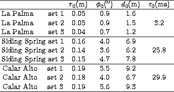
A rapid variation in Cn2(h) far in excess of that expected due to noise alone is also noticeable from these results. The scale of these variations are a typical feature of all of the Cn2(h) profiles we have examined so far such that the strength of the optical turbulence due to any particular layer can fluctuate by as much as a factor of 2 or 3 within tens of seconds. One notable difference in the example profiles shown is that between the strength of those of the JKT in La Palma (a) and the others, and this is reflected in the parameters given in Table 1. Not only is the integrated Cn2(h) close to an order of magnitude greater but the speed of the dominant layer in the upper atmosphere is also very much larger.
Figure 12 illustrates the longer term changes in Cn2(h) that
have been commonly
observed. Shown here are three bar-plot profiles from the Siding Springs site
taken
during the same observing run as above. Each profile was calculated from a
four minute block of data (thus allowing a higher SNR than previously) with each
block separated in time by 40 minutes.
As can be seen, the structure of turbulent layers at low altitudes
remains reasonably consistant throughout this period, whereas at high altitudes
this is
not the case. The impact of these changes in layer structure upon angular and
focal
anisoplanatism is emphasised graphically in Fig. 13 where the same
profiles
are shown after scaling with h5/3. Although the value of r0
remains
between 14.5 and 16.0 cm, the value of ![]() and d0 increase
steadily from 3.0'' to 5.0'' and from 5.3 m to 8.8 m respectively.
This figure also serves to emphasise again the high degree of discretisation
that
can occur within a turbulent atmosphere.
and d0 increase
steadily from 3.0'' to 5.0'' and from 5.3 m to 8.8 m respectively.
This figure also serves to emphasise again the high degree of discretisation
that
can occur within a turbulent atmosphere.
Copyright The European Southern Observatory (ESO)