Some snapshots of the system configuration in the head-on collision experiment are illustrated in Figs. 3, 4 and 5. The first frame (Fig. 3) corresponds to the system configuration after 250 kyr from the beginning. The orbital plane for the three collisions is the xy-plane, with the x-axis containing the mass-center of both initial clouds.
In Figs. 4 and 5 respectively the face-on and edge-on configuration of the collision remnants after 3.75 Myr are shown. These plots reveal the clumped nature of the shock remnants in the head-on case. At this time, the internal parts (darker) of the remnants are approximately isothermal around 10 K, and the outer parts remain at approximately 20 K.
The shock density-profile at 1.5 Myr is shown in detail
in the linear gray-scale as illustrated in Fig. 6.
The picture was interpolated along a longitudinal slice of 0.25 pc in thickness.
The shock aspect would appear thicker if the densities were
integrated along the whole line-of-sight.
The density peak was ![]() cm-3 at the hottest configuration of the
shock.
Latter it reached
cm-3 at the hottest configuration of the
shock.
Latter it reached ![]() cm-3 in some
clumps as shown in Figs. 9 and 10.
cm-3 in some
clumps as shown in Figs. 9 and 10.
Figure 7 reveals the temperature profile in a logarithmic gray-scale,
averaged in the same
longitudinal slice of Fig. 6.
In Fig. 8, corresponding to the same situation of Fig. 7,
we can see in more detail that each cloud has a core forming in its center.
These two proto cores are approximately isothermal, with ![]() 14 K.
The hottest spot corresponds to
14 K.
The hottest spot corresponds to ![]() K.
After 3 Myr the shocked region becomes cooler than the surrounding gas.
This behavior is mainly due to the strong dependence of the CO and the
H2 cooling on
density.
The Dalgarno and McCray model was relevant
in the first two steps of the experiments,
mainly the head-on, where temperatures reached values as high as
K.
After 3 Myr the shocked region becomes cooler than the surrounding gas.
This behavior is mainly due to the strong dependence of the CO and the
H2 cooling on
density.
The Dalgarno and McCray model was relevant
in the first two steps of the experiments,
mainly the head-on, where temperatures reached values as high as ![]() K.
The temperatures in the shock front reached a maximum of approximately
3000 K.
Exceptionally, a unique particle reached,
along these two initial steps,
a temperature
of approximately 5000 K.
K.
The temperatures in the shock front reached a maximum of approximately
3000 K.
Exceptionally, a unique particle reached,
along these two initial steps,
a temperature
of approximately 5000 K.
We analyzed structures (e.g., clumps, shock etc.) by exhaustively creating subsets of the original output files, sorted by density, temperature, z-axis etc., so that we could visually identify structures that appeared in the graphs for a given range of the control parameter (e.g., density). From this preliminary analysis, we could isolate some relevant structures as those shown in Fig. 8.
After the shock extinction, the head-on collision remnants revealed a clumped
aspect
as shown in Figs. 4 and 5.
Some cores formed in the denser parts of the formed system:
Fig. 9 detached the denser parts of Fig. 4 and
Fig. 10
shows a zoom of the densest core of Fig. 9,
where only particles with densities greater
than or equal to half the maximum
density (
![]() cm-3) are shown.
All particles shown in Figs. 9 and 10
have the same temperature
T=11.68 K, which is colder than its surroundings.
cm-3) are shown.
All particles shown in Figs. 9 and 10
have the same temperature
T=11.68 K, which is colder than its surroundings.
The off-center collisions were performed with two distinct impact parameters, b1=5.0 pc (25% off-center) and b2=10 pc (50% off-center), where the maximum impact parameter for the present work is naturally b=20 pc. The 50% off-center collision was found qualitatively similar to the previous case. However, the effects of the shock propagated by the collision on the individual cloud structure was significantly small than in the 25% off-center case, so that only the latter is illustrated here (Figs. 12 and 13).
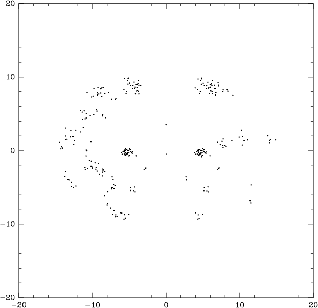 |
Figure 8: Particle configuration corresponding to the situation in Fig. 7 but showing only particles with temperatures below 16 K. This plot reveals a core forming in the central parts of each cloud |
 |
Figure 9:
Particle configuration corresponding to the situation in Fig. 4
but showing only particles with number
densities greater
than or equal to half the maximum
density (
|
 |
Figure 10:
A zoom in the densest core of the cluster showed in Fig. 9.
The maximum number-density particle
is plotted with a black square,
which values
|
 |
Figure 11: 2D Plot of the particle configuration projected onto the orbital plane for the experiment with impact parameter of 5 pc (25% off-center) after 0.25 Myr |
 |
Figure 12:
2D Plot of the particle configuration projected onto the orbital plane
for the experiment with impact parameter of 5 pc (25% off-center)
case after |
 |
Figure 13: The corresponding situation of Fig. 12 but projected in a perpendicular direction to the orbital plane |
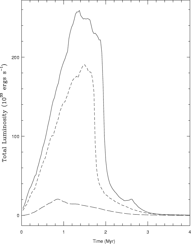
The rate of energy loss (cloud luminosity)
in the three experiments is shown
as a function of time in Fig. 14.
Each plot reflects the energy-loss dependence on the impact parameter.
The luminosity variation is smoother for off-center collisions.
The head-on collision exhausted about 83% of the initial kinetic energy
against 38% in the 50% off-center case.
We observed that, although the thermal energy reached by the head-on case
is greater than the one reached by the
off-center collision, the head-on case became colder after about 3.5 Myr.
Stronger collisions produce denser regions,
which cool faster since the
cooling mechanism depends strongly on density.
The shock behavior was essentially driven by the cooling mechanism and by the
dependence of the H
![]() H transition on the temperature.
The shock resolution was limited by the kernel's width, which
depends on the number of
neighbors.
H transition on the temperature.
The shock resolution was limited by the kernel's width, which
depends on the number of
neighbors.
Copyright The European Southern Observatory (ESO)