The data are based on the double radio source compilation of Nilsson et al. (1993) with new objects added and some old values renewed using recent studies. To be included in our database the source was required to have FR II type morphology. Thus unresolved sources and sources with complex, FR I or one-sided (D2) morphology were excluded. Special emphasis was given to finding the best published radio maps for unambiguous classification. The small sources with angular sizes of a few arcsec pose a problem since they are sometimes difficult to classify into one-sided and two-sided sources. In these cases the appearance of the radio structure and position of the optical identification with respect to radio emission were used as indicators of the correct classification.
The resulting database contains 1038 sources of which 544 are galaxies, 365 are quasars and 129 have no optical identification. The redshift is known for 334 galaxies and 335 quasars. As a whole the database is quite heterogeneous: part of the data are incomplete, e.g. the sources have not been optically identified or flux information is missing, and many sources have entered the database from studies in which the sources have not been selected in a systematic manner. However, a statistically complete sample with relatively complete structural information can be extracted from the database.
The complete sample in question contains all double radio sources in
the radio source compendium of Herbig & Readhead
(1992). This compendium is based on three complete samples,
namely 1) the revised 3C sample of Laing et al. (1983,
the "LRL sample''), 2) the complete sample of radio sources of
Peacock & Wall (1981), the "PW sample'' and 3) the
complete sample of S4 and S5 sources by Pearson & Readhead
(1988), the "PR sample''. The first sample is selected to
include sources with ![]() 10 Jy and
10 Jy and ![]() , the second
, the second ![]() 1.5 Jy and
1.5 Jy and ![]() and the third
and the third ![]() 1.3 Jy and
1.3 Jy and ![]() . Sources that are closer than 10
. Sources that are closer than 10![]() to the galactic
plane are excluded in all three samples. The statistically complete
subsample of the database, hereafter the "HR sample'', includes 159
sources of 256 in the Herbig & Readhead (1992)
compendium. Of the remaining 97 sources 53 are unresolved, 29 are FR I type,
6 are D2 type, 5 have a complex structure and for 4 sources
the radio structure is unknown. The HR sample consists of radio
sources that have been observed in greatest detail and thus
high quality maps were available for the most part of the
sample. Essentially the same sample could have been formed by
selecting sources from the LRL sample alone (138 sources in the HR
sample come from this sample). This is because the LRL sample
is selected at a lower frequency than the the two other samples
and thus the lobe dominated sources that have steeper spectra
tend to be selected more efficiently. The HR sample contains
110 radio galaxies, 47 radio quasars and two sources with
unknown optical identification. The redshift is known for 155
sources (97% of the sample).
to the galactic
plane are excluded in all three samples. The statistically complete
subsample of the database, hereafter the "HR sample'', includes 159
sources of 256 in the Herbig & Readhead (1992)
compendium. Of the remaining 97 sources 53 are unresolved, 29 are FR I type,
6 are D2 type, 5 have a complex structure and for 4 sources
the radio structure is unknown. The HR sample consists of radio
sources that have been observed in greatest detail and thus
high quality maps were available for the most part of the
sample. Essentially the same sample could have been formed by
selecting sources from the LRL sample alone (138 sources in the HR
sample come from this sample). This is because the LRL sample
is selected at a lower frequency than the the two other samples
and thus the lobe dominated sources that have steeper spectra
tend to be selected more efficiently. The HR sample contains
110 radio galaxies, 47 radio quasars and two sources with
unknown optical identification. The redshift is known for 155
sources (97% of the sample).
A larger subsample with useful amount of flux and structural
information can be extracted by selecting all sources in the database with
![]() 2.5 Jy (hereafter the "2.5 Jy sample'').
This is close to the 2 Jy limit that was used in forming the 4C sample
(Pilkington & Scott 1967; Gower et al.
1967) and the same limit that was used by Hooley et al.
(1978) in forming their radio quasar sample.
Thus it is not surprising that 75% of the 2.5 Jy sample consists
of 3C and 4C sources. Note that the HR sample is a
subsample of the 2.5 Jy sample, except for 3 sources in the former
that do not occur in the latter. The 2.5 Jy sample
contains 722 sources of which 411 are radio galaxies, 234 are radio
quasars and 77 have no optical identification.
The redshift is known to 501 sources (69% of the sample).
2.5 Jy (hereafter the "2.5 Jy sample'').
This is close to the 2 Jy limit that was used in forming the 4C sample
(Pilkington & Scott 1967; Gower et al.
1967) and the same limit that was used by Hooley et al.
(1978) in forming their radio quasar sample.
Thus it is not surprising that 75% of the 2.5 Jy sample consists
of 3C and 4C sources. Note that the HR sample is a
subsample of the 2.5 Jy sample, except for 3 sources in the former
that do not occur in the latter. The 2.5 Jy sample
contains 722 sources of which 411 are radio galaxies, 234 are radio
quasars and 77 have no optical identification.
The redshift is known to 501 sources (69% of the sample).
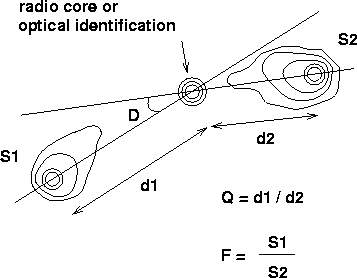 |
Figure 1: A schematic radio map showing the definition of symmetry parameters Q, D and F used in this paper |
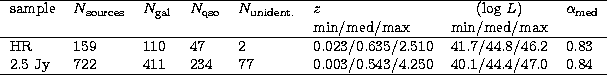
The data are given in Tables 1 and 2. Table 1 contains the sources in the HR and 2.5 Jy samples and Table 2 contains the rest of the sources. When calculating linear sizes and luminosities H0 = 50 km s-1 Mpc-1 and q0 = 0.5 has been assumed.
The organization of columns in Table 1 is as follows:
Column (1) - IAU name of the source.
Column (2) - Other name of the source.
Column (3) - Redshift of the optical identification, spectroscopically measured in all cases.
Column (4) - Largest angular size of the radio structure, measured as the angular distance between the outermost hotspots.
Column (5) - Spectral index ![]() between 178 MHz and 5 GHz,
calculated from flux data at these frequencies (flux
between 178 MHz and 5 GHz,
calculated from flux data at these frequencies (flux ![]() ).
).
Column (6) - Projected linear size of the source in kpc.
Column (7) - Luminosity between 10 MHz and 10 GHz in the rest frame of
the source,
calculated from flux data at 178 MHz and 5 GHz and assuming a single
power-law spectrum over the whole frequency range. In the rare cases when
data were available for one frequency only, the median spectral index
of the database ![]() = 0.8 was used. Herbig
& Readhead (1992) list multifrequency flux data and
luminosities that could have been used for the HR sample here, but
in order to treat all data in the same manner the single power-law
approximation and the formulae in
Nilsson et al. (1993) were used in all instances.
= 0.8 was used. Herbig
& Readhead (1992) list multifrequency flux data and
luminosities that could have been used for the HR sample here, but
in order to treat all data in the same manner the single power-law
approximation and the formulae in
Nilsson et al. (1993) were used in all instances.
Column (8) - Flux of the core component at 5 GHz. In some cases this is estimated from the radio map.
Column (9) - Spectral index of the core near 5 GHz, defined in the
same manner as for ![]() above.
above.
Column (10) - The relative strength of the core at 5 GHz, defined here
as the radio power of the core divided by the total power of the source.
The radio power P is calculated from the expression.
| (1) |
Column (11) - The arm length ratio Q, defined as the ratio of the distances of the outermost hotspots at opposite sides from the radio core or the optical identification (Fig. 1). Q > 1 by definition.
Column (12) - The bending angle D.
Column (13) - The flux ratio F, defined as
| F = S1 / S2, | (2) |
Column (14) - The frequency at which S1 and S2 were measured (in most cases 5 GHz).
Column (15) - flux %, a value defined as
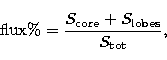 |
(3) |
Column (16) - Optical identification: G = galaxy, Q = quasar and - = unidentified.
Column (17) - Reference to the radio map. An asterisk indicates that no radio map was available and the symmetry data were extracted from tabular material.
Column (18) - References.
Column (19) - Sample membership: A = HR sample, B = 2.5 Jy sample.
The organization of Table 2 is similar, except that no column for sample membership (Col. 19) is given.
Table 3 summarizes the properties of the two samples and Fig. 2 shows the position of the sources with known redshift in the redshift - luminosity plane. The redshift distributions of the two samples are very similar; the difference in median redshift in Table 3 is not significant (p = 0.28 with the Kolmogorov-Smirnov test), although most of the high redshift sources (z > 1.5) belong to the 2.5 Jy sample. The luminosity difference, in contrast, is significant (p < 0.01) . Both samples thus probe the redshift space in a similar manner but at each z the 2.5 Jy sample reaches fainter luminosities than the HR sample, which is expected because of the fainter flux threshold.
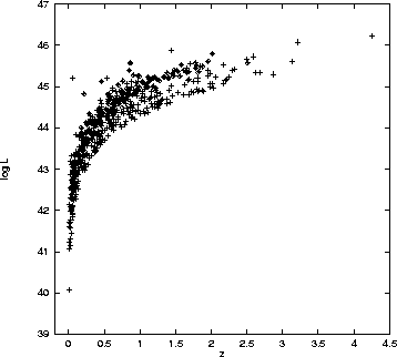 |
Figure 2: The redshift - luminosity diagram of the HR sample (diamonds) and the 2.5 Jy sample (plus signs) |
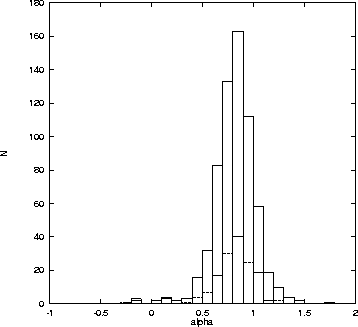 |
Figure: The distribution of spectral index between 178 MHz and 5000 MHz for the HR sample (dashed line) and 2.5 Jy sample (solid line) |
Finally, in Fig. 3 the spectral index
![]() distribution for the HR and 2.5 Jy samples is shown.
The spectral index is concentrated around
distribution for the HR and 2.5 Jy samples is shown.
The spectral index is concentrated around ![]() = 0.8, which is expected
because both samples contain mainly lobe-dominated FR II sources.
There is also a small flat spectrum tail that is caused by triple
sources with a very strong core and weak lobes.
= 0.8, which is expected
because both samples contain mainly lobe-dominated FR II sources.
There is also a small flat spectrum tail that is caused by triple
sources with a very strong core and weak lobes.
Acknowledgements
This work has been supported by the Academy of Finland.
Copyright The European Southern Observatory (ESO)