The strengths of absorption spectral features have been measured in different
ways so far. However, although with slight differences among them, most
authors have employed line-strength indices with definitions close to the
classical expression for an equivalent width:
![]()
where ![]() is the observed spectrum and
is the observed spectrum and ![]() is the local
continuum usually obtained by interpolation of
is the local
continuum usually obtained by interpolation of ![]() between two
adjacent spectral regions (e.g. Faber 1973;
Faber et al. 1977; Whitford &
Rich 1983; Gorgas 1987;
Brodie & Huchra 1990; González 1993;
Rose
1994). In order to avoid subjective determinations of the local continuum,
line-strength indices following Eq. (1 (click here)), referred
as atomic indices, are completely characterized by three wavelength
regions (bandpasses). The spectral feature of interest is covered by the
central bandpass whereas the other two bandpasses, located towards the red
and blue of the central region, are employed to define the continuum
reference level through a linear interpolation. As pointed out by
Geisler
(1984) (see also Rich 1988), at low spectral resolution a pseudo-continuum is
measured instead of a true continuum.
between two
adjacent spectral regions (e.g. Faber 1973;
Faber et al. 1977; Whitford &
Rich 1983; Gorgas 1987;
Brodie & Huchra 1990; González 1993;
Rose
1994). In order to avoid subjective determinations of the local continuum,
line-strength indices following Eq. (1 (click here)), referred
as atomic indices, are completely characterized by three wavelength
regions (bandpasses). The spectral feature of interest is covered by the
central bandpass whereas the other two bandpasses, located towards the red
and blue of the central region, are employed to define the continuum
reference level through a linear interpolation. As pointed out by
Geisler
(1984) (see also Rich 1988), at low spectral resolution a pseudo-continuum is
measured instead of a true continuum.
Line-strength indices are sometimes measured in magnitudes using:
![]()
where ![]() is the width of the central bandpass. These
line-strengths, referred as molecular indices since they are used for
molecular-band features, are defined with the help of broad bandpasses with
the continuum regions located far from the central feature. On the other
hand, atomic indices, which measure the absorption of atomic spectral
features, have narrower and neighboring bandpasses.
is the width of the central bandpass. These
line-strengths, referred as molecular indices since they are used for
molecular-band features, are defined with the help of broad bandpasses with
the continuum regions located far from the central feature. On the other
hand, atomic indices, which measure the absorption of atomic spectral
features, have narrower and neighboring bandpasses.
Throughout this
paper we use the definitions given by González (1993),
in which atomic
(![]() ) and molecular (
) and molecular (![]() ) indices are defined as follows:
) indices are defined as follows:
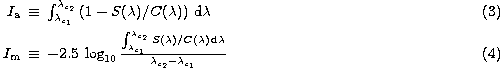
where ![]() and
and ![]() are the limits of the central
bandpass (in Å). The local pseudo-continuum
are the limits of the central
bandpass (in Å). The local pseudo-continuum ![]() is derived by
is derived by
![]()
![]()
![]()
being ![]() ,
, ![]() ,
, ![]() , and
, and ![]() the limits of the blue and red bandpasses respectively.
the limits of the blue and red bandpasses respectively.
Although simplified versions of these expressions (i.e. considering a constant continuum flux along the central bandpass, or replacing the integrals by mean values) yield similar results at intermediate resolution, the more accurate formulae must be favoured in order to guarantee the comparisons with high-resolution high-S/N (signal-to-noise ratio) spectra (specially for asymmetric indices, as already noted by Worthey et al. 1994).
Probably, the most widely index definition system employed so far is that established by the Lick group (Burstein et al. 1984, 1986; Faber et al. 1985; Gorgas et al. 1993; Worthey et al. 1994). In Table 1 (click here) we list the exact definitions (as given by Trager 1997) for the 21 indices which constitute the extended Lick system (see also González 1993). This table also includes the definitions given by Dıaz et al. (1989) for the CaII triplet in the near-infrared. In this paper we will concentrate on the analysis of line-strength errors for these particular indices, although the derived analytical expressions are valid for any general index following Eqs. (3 (click here)) or (4 (click here)).
Another interesting spectral feature which will be studied in this paper
is the amplitude of the ![]() -Å break
(D4000). We adopt here the definition given by Bruzual (1983):
-Å break
(D4000). We adopt here the definition given by Bruzual (1983):
![]()
This index
can be considered as a pseudo-color, being the combination of ![]() and
and
![]() due to historical reasons.
due to historical reasons.
| Index Name | Central Bandpass ( | Continuum Bandpasses ( | ci | |
| 0mm[0mm][3mm]Atomic Indices | c1 | c2 | ||
| Ca4227 | 4222.250-4234.750 | 4211.000-4219.750 | 4.604 | 0.3684 |
| 4241.000-4251.000 | ||||
| G4300 | 4281.375-4316.375 | 4266.375-4282.625 | 8.537 | 0.2439 |
| 4318.875-4335.125 | ||||
| Fe4383 | 4369.125-4420.375 | 4359.125-4370.375 | 3.220 | 0.2580 |
| 4442.875-4455.375 | ||||
| Ca4455 | 4452.125-4474.625 | 4445.875-4454.625 | 7.038 | 0.3128 |
| 4477.125-4492.125 | ||||
| Fe4531 | 4514.250-4559.250 | 4504.250-4514.250 | 1.299 | 0.2511 |
| 4560.500-4579.250 | ||||
| Fe4668 | 4634.000-4720.250 | 4611.500-4630.250 | 7.757 | 0.2059 |
| 4742.750-4756.500 | ||||
|
H | 4847.875-4876.625 | 4827.875-4847.875 | 7.301 | 0.2539 |
| 4876.625-4891.625 | ||||
| Fe5015 | 4977.750-5054.000 | 4946.500-4977.750 | 6.455 | 0.2158 |
| 5054.000-5065.250 | ||||
| Mgb | 5160.125-5192.625 | 5142.625-5161.375 | 8.032 | 0.2472 |
| 5191.375-5206.375 | ||||
| Fe5270 | 5245.650-5285.650 | 5233.150-5248.150 | 9.250 | 0.2313 |
| 5285.650-5318.150 | ||||
| Fe5335 | 5312.125-5352.125 | 5304.625-5315.875 | 0.741 | 0.2685 |
| 5353.375-5363.375 | ||||
| Fe5406 | 5387.500-5415.000 | 5376.250-5387.500 | 7.256 | 0.2893 |
| 5415.000-5425.000 | ||||
| Fe5709 | 5696.625-5720.375 | 5672.875-5696.625 | 6.362 | 0.2679 |
| 5722.875-5736.625 | ||||
| Fe5782 | 5776.625-5796.625 | 5765.375-5775.375 | 6.134 | 0.3067 |
| 5797.875-5811.625 | ||||
| NaD | 5876.875-5909.375 | 5860.625-5875.625 | 8.113 | 0.2496 |
| 5922.125-5948.125 | ||||
| Ca1 | 8483.000-8513.000 | 8447.500-8462.500 | 8.852 | 0.2951 |
| 8842.500-8857.500 | ||||
| Ca2 | 8527.000-8557.000 | 8447.500-8462.500 | 8.330 | 0.2777 |
| 8842.500-8857.500 | ||||
| Ca3 | 8647.000-8677.000 | 8447.500-8462.500 | 7.750 | 0.2583 |
| 8842.500-8857.500 | ||||
| 0mm[0mm][3mm]Molecular Indices | c3 | |||
| CN1 | 4142.125-4177.125 | 4080.125-4117.625 | 0.2241 | |
| 4244.125-4284.125 | ||||
| CN2 | 4142.125-4177.125 | 4083.875-4096.375 | 0.2691 | |
| 4244.125-4284.125 | ||||
| Mg1 | 5069.125-5134.125 | 4895.125-4957.625 | 0.1662 | |
| 5301.125-5366.125 | ||||
| Mg2 | 5154.125-5196.625 | 4895.125-4957.625 | 0.1933 | |
| 5301.125-5366.125 | ||||
| TiO1 | 5936.625-5994.125 | 5816.625-5849.125 | 0.1824 | |
| 6038.625-6103.625 | ||||
| TiO2 | 6189.625-6272.125 | 6066.625-6141.625 | 0.1568 | |
| 6372.625-6415.125 | ||||