The primary mirror of the telescope is in general a concave paraboloid.
We consider a paraboloid, having its axis coinciding with the Z-axis and
the vertex coinciding with the origin of the co-ordinate system. We consider one
incident ray in the ZX plane, making an angle ![]() with Z axis (and
with Z axis (and
![]() with X axis) and passing through the origin. The Y axis
will be perpendicular to this ray. The direction cosine (henceforth d.c.)
of the incident ray can be written as:
with X axis) and passing through the origin. The Y axis
will be perpendicular to this ray. The direction cosine (henceforth d.c.)
of the incident ray can be written as:
![]()
Now we consider a beam of rays which are parallel to this above
ray and coming from a celestial object having a field angle ![]() with
respect to the telescope axis. The rays which lie in the outer periphery
of this beam, will be incident on the parabolloid mirror at points defining
a circle, with radius h1 and the centre of the circle lying on the Z axis.
(where
with
respect to the telescope axis. The rays which lie in the outer periphery
of this beam, will be incident on the parabolloid mirror at points defining
a circle, with radius h1 and the centre of the circle lying on the Z axis.
(where ![]() is the diameter of the paraboloid mirror). The plane defined by
this circle will have Z axis perpendicular to it. The (x,y) co-ordinates of
any point on this circle can be expressed as
is the diameter of the paraboloid mirror). The plane defined by
this circle will have Z axis perpendicular to it. The (x,y) co-ordinates of
any point on this circle can be expressed as ![]() .
In this case
.
In this case ![]() is the azimuthal angle of the ray. For example the rays
which are contained in the ZX plane will have
is the azimuthal angle of the ray. For example the rays
which are contained in the ZX plane will have ![]() . We further
assume that f1 is the f-number of the primary mirror, which is nothing but
the ratio of focal length to the diameter.
. We further
assume that f1 is the f-number of the primary mirror, which is nothing but
the ratio of focal length to the diameter.
Now the equation of the above paraboloid can be expressed as:
![]()
Substituting the values ![]() , we get
the Z coordinate of the point of incidence as
, we get
the Z coordinate of the point of incidence as ![]() .
Now the d.c. of
the normal at this point
.
Now the d.c. of
the normal at this point ![]() can be
expressed as:
can be
expressed as:

The angle of incidence (pi) between the normal and incident ray can be expressed as:
![]()
The d.c of the reflected ray ![]() ,
which makes an
angle pi with the normal and
,
which makes an
angle pi with the normal and ![]() with the incident ray can be expressed
as:
with the incident ray can be expressed
as:
Now we shall find the d.c. of the other vectors connected to the incident plane. The electric field vectors of the incident and reflected rays can be resolved in two directions, one perpendicular to the plane of incidence (s-direction) and the other orthogonal to the s-direction (we call it p-direction). Actually there are two p-directions, one corresponds to the incident ray (pi-direction) and the other corresponds to the reflected ray (pr-direction). While discussing reflection on primary mirror, we refer to these directions as ps, ppi and ppr.
While considering the reflection on the secondary mirror, we shall denote the corresponding quantities as ss, spi and spr vectors.
The ps-vector is actually perpendicular to the plane containing vectors
![]() and
and ![]() .
Therefore the d.c. of the ps-vector
.
Therefore the d.c. of the ps-vector ![]() will be
proportional to
will be
proportional to
![]()
After proper substitution and normalisation, these values can be determined as:

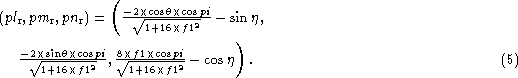
Similarly the ppi-vector with directions (plpi, pmpi,
pnpi),
is perpendicular to the directions ![]() and
and
![]() and therefore, one can derive
and therefore, one can derive
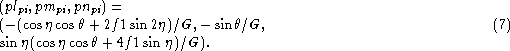
The ppr-vector with direction (plpr, pmpr, pnpr), is
perpendicular to the directions ![]() and
and
![]() and one can similarly derive
and one can similarly derive

where we have substituted
